Linux File System Write

Linux Content Index

File System Architecture – Part I
File System Architecture– Part II
File System Write
Buffer Cache
Storage Cache

Linux file write methodology is specific to particular file systems. For example, JFFS2 will sync data within the user process ‘context’ itself (inside write_end call), while file systems like UBIFS, LogFS, Ext & FAT tends to create dirty pages and let the background flusher task manage the sync.

These two methodologies come with their own advantages, but usage of the second method leads to Linux kernel exhibiting certain quirks which might drastically impact the write throughput measurements.

Linux File Write

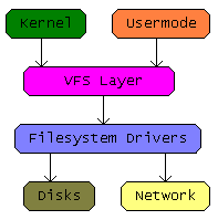
The above diagram does give an overview of the design, there are in fact two main attributes to this architecture:

COPY : User space data is copied into a kernel page associated with the file and marked as dirty via“write_begin” and “write_end” file system call backs, they are in fact invoked for every “write” system call made by the user process. So while they are indeed kernel mode functions they get executed on behalf of the user space process which in turn simply waits on the the system call. The sequence is illustrated below:

    write_begin()  /* Informs FS about the number of bytes being written */
    mem_copy()    /* Copies data to kernel page cache.*/
    write_end()     /* Copied kernel page marked as dirty and FS internal */
/*  meta information is updated */

&

Write-Back : The Linux kernel will spawn a flusher task to write these above created dirty pages into the storage. For that this newly spawned task would typically invoke file system specific “writepage” or “writepages” call-back.

Some Nitty-Gritty Details

The call-backs mentioned above are specific to the file system and are essentially registered during its initialization with kernel. You might have noticed that the above design almost resemble a classic producer consumer scenario, but there are certain nuances:

Lower Threshold: The flusher task (consumer) is spawned only when a certain percentage of page cache becomes dirty. So there is indeed a lower threshold (configured in /proc/sys/vm/dirty_background_ratio) for spawning this task. Please note that it can also be invoked after an internal time-out. So even if the dirty pages are in small numbers, they are not kept around in volatile memory for a long time.

Higher Threshold: Once a certain high percentage of page cache is dirtied by a user process (producer), this process is forced to sleep to avoid the kernel running out of memory. Such a user process is not unhooked from this involuntary sleep until the flusher task catches up and brings down the dirty page levels to acceptable limits. This way kernel tends to push back on the process which comes with a massive capacity to write data. This higher threshold can be specified by writing to /proc/sys/vm/dirty_ratio.

So between the above mentioned lower and upper thresholds the system tends to have two concurrent tasks, one which dirty the pages with contents and the other which cleans them up with a write back. If there are too many dirty pages being created, then Linux might also spawn multiple flusher tasks. Seems like this design might scale well on SMP architectures with multiple storage disk paths.

We could bring some more clarity with the exposition of code level details. The critical aspect of the above mechanism is implemented in the below mentioned balance_dirty_pages (page-writeback.c) which gets invoked after “write_end” call inside kernel.

The function audits the number of dirty pages in the system and then decides whether the user process should be stalled.

static void balance_dirty_pages (struct address_space *mapping, unsigned long write_chunk)

{
int pause = 1;


……
………
for (;;)

{
….
……         /* Code checks for dirty page status and breaks out of the loop only if the dirty page ratio has gone down */
……..

io_schedule_timeout(pause);

/*
* Increase the delay for each loop, up to our previous
* default of taking a 100ms nap.
*/
pause <<= 1; if (pause > HZ / 10)
pause = HZ / 10;
}
}

The argument ‘pause’ to the function io_schedule_timeout specify the sleep time in terms of jiffies while the big for (;;) loop repeatedly checks the dirty page ratio after each sleep cycle and if there is no ample reduction in that then the sleep time is doubled until it reaches 100mS, which is in fact the maximum time the ‘producer‘ process can be forced to sleep. This algorithm is executed during file writes to ensure that no rogue process goes amok consuming the full page cache memory.

The Gist

We can attribute considerable significance for the above mentioned upper and lower thresholds, if they are not fine tuned for the system specific use cases then the RAM utilization will be far from optimal. The particulars for these configurations will depend on RAM size plus how many processes will concurrently initiate file system writes, how big these writes will be, file sizes being written, typical time intervals between successive file writes etc.

A file system mounted with syncs off is meant to utilize page cache for buffering. Optimal write speeds will mandate that the upper threshold be large enough to buffer the full file while allowing seamless concurrent write backs, otherwise the kernel response time for user process writes will be erratic at best.

Another critical aspect is that the writepage should have minimal interference with write_begin & write_end, only then the flusher task write backs can happen with least friction with regards to the user process which is constantly invoking the latter two functions. If they share some resource, then eventually the user process and the flusher task will end up waiting on each other and the expected quick response time of an asynchronous buffered page cache write will not be materialized.

Linux Buffer Cache and Block Device

Linux Content Index

File System Architecture – Part I
File System Architecture– Part II
File System Write
Buffer Cache
Storage Cache

Working on a flash file system port to Linux kernel mandates a good understanding of its buffer management, sometimes the excavation of internals can be a bit taxing but it’s needed for executing a well integrated port. Hopefully this write up will help someone who is looking to get a good design overview of the kernel buffer/page cache.

VFS work on top of pages and it allocates memory with a minimum granularity of the page size (usually 4K) but a storage device is capable of an I/O size much smaller than that (typically 512 bytes).  A case where the device write granularity is set to page size can result in redundant writes, for example if an application modifies 256 bytes of a file then the corresponding page in cache is marked as dirty & flushing of this file results in a transfer of 4K  bytes because there is no mechanism for the cache to identify the dirty sector within this dirty PAGE.

Buffer Cache bridges the page and the block universes, a page associated with a file  will be divided into buffers & when a page is modified only the corresponding buffer is set as dirty, so while flushing only the dirty buffer gets written. In other words a buffer cache is an abstraction done on top of a page, its simply a different facet to the same RAM memory. The data structure called “buffer_head” is used for managing these buffers, the below diagram is a rather crass depiction of this system.

Buffer Cache can traverse the list of these buffers associated with a page via the “buffer_head” linked list and identify their status; note that the above diagram assumes a buffer size of 1K.

How about streaming writes?

When dealing with huge quantities of data, the method of sequential transfer of small sectors can lead to a pronounced overall read-write head positioning delay and there is also this additional overhead due to multiple set up and tear down cycles of transfers.

Lets consider an example of a 16K buffer write operation consisting of four 4K pages, the memory mapping for these 4 pages are given in the table below. For example, sectors 0 to 3 of a file is located in the RAM address 0x1000 to 0x1FFF, and it’s mapped to storage blocks 10, 11, 12 & 13.

Blindly splitting the 16K into 16 buffers and writing them one by one will result in as many transfer set ups and teardowns, and also an equivalent number of read-write head position delays.

How about we reorder the writing of pages in the following manner?

Page1 >>> Page 3 >>> Page 2 >>> Page 4

The above sequence is the result of sorting the pages in an increasing order of block mappings, ie: from 10 till 25, a closer look will also reveal that the adjacent transfers have addresses running from 0x1000 till 0x4FFF and hence contiguous in RAM memory. This results in an uninterrupted  transfer of 16K bytes, which seems to be the best case optimization.

How does Linux achieve this gathering?

Let’s try to comprehend how bock driver subsystem skews application’s order of writes to achieve the previously described optimization.

Algorithm implemented by the above architecture is explained below

Step 1: A Buffer is encapsulated in a BIO structure.
File system buffers are encapsulated in a BIO structure  (submit_bh function can give the details). At this stage all the 16 buffers in our example are wrapped inside its corresponding BIO struct. We can see the mapping in the below table.

Step 2: A BIO is plugged into a request.
BIOs are sequentially submitted to the below layers and the those mapped to adjacent blocks are clubbed into a single “request“.  With the addition of the request struct we have the below updated mapping table, as you can see “Request 0” combines BIO 0,1,2 & 3.

Prior to adding the requests to the global block driver queue there is an intermediate task_struct queue, this is an obvious optimization aimed at clubbing the adjacent BIOs into one request and to minimize contention for the block driver queue. Yes, a global queuing operation cannot happen in parallel to another queuing or a de-queuing.

Step 3: Merge requests into the global queue.
Merging a request into the global queue will reorder and coalesce the adjacently mapped “requests” into one and in our case we will finally have only one single request which will envelop all the BIOs.

Step 4:Finally we need to identify the contiguous memory segments.
Block device driver will identify consecutive memory segments across adjacent BIOs and club them before initiating a transfer, this will reduces the I/O setup – tear down cycles. So we will have a segment attribute added to our final table which is given below.

The block device driver can also have a request scheduler, this scheduler algorithm will prioritize and pick requests to be de-queued from the global queue for I/O processing. Please note that the steps for read requests also follow the above framework.

Inference

The above bells and whistles are irrelevant when it comes to flash memories, so avoiding all this baggage might make a lot of sense.

Linux File System Stack – 2

Linux Content Index

File System Architecture – Part I
File System Architecture– Part II
File System Write
Buffer Cache
Storage Cache

A Linux file system is expected to handle two types of data structure species — Dentries & Inodes. They are indeed the defining characteristic of a file system running inside the Linux kernel. For example a path “/bm/celtic” contains three elements, “/” , “bm” & “celtic”, so each will have its own own dentry and inode. Among a lot of other information a dentry encapsulates the name, a pointer to the parent dentry and also a pointer to the corresponding inode.

What happens when we type “cd /bm/celtic”?

Setting the current working directory involves pointing the process “task_struct” to the dentry associated with “celtic”, locating that particular entry involves the following steps.

  1. “/” at the beginning of the string indicates root
  2. Root dentry is furnished during file system mount, so VFS has a point where it can start its search for a file or a directory.
  3. A file system module is expected to have the capability to search for a child when the parent dentry is provided to it. So VFS will request the dentry for “bm” by providing its parent dentry (root).
  4. It’s up to the file system module to find the child entry using the parent dentry. Note that the parent Dentry also has a pointer to its own inode which might hold the key.

The above sequence of steps will be repeated recursively. This time the parent will be  “bm” and “celtic” will be the child, in this manner VFS will generate a list of Dentries associated with a path.

Linux is geared to run on sluggish hard disks supported with relatively large DRAM memories. This might mean that there is this ocean of Dentries and Inodes cached in RAM & whenever a cache miss is encountered, VFS tries to access it using the above steps by calling the file system module specific “look_up” function.

Fundamentally a file system module is only expected to work on top of inodes, Linux will request operations like creation and deletion of inodes, look up of inodes, linking of inodes, allocation of storage blocks for inodes etc.

Parsing of paths, control cache management are all abstracted in kernel as part of VFS and buffer management as part of block driver framework.

How about writing to new file?

  1. User space communicates the buffer to be written using the “write” system call.
  2. VFS then allocates a kernel page and associates that with the write offset in the “address_space” of that inode, each inode has its own address_space indexed by the file offset.
  3. Every write needs to eventually end up in the storage device so the new page in the RAM cache will have to be mapped to a block in the storage device. For this VFS calls the “get_block” interface of a the file system module, which establishes this mapping.
  4. A copy_from_user_space routine moves the user contents into that kernel page and marks it as dirty.
  5. Finally the control returns to the application.

Overwriting contents of a file differ in two aspects – one is that the offset being written to might already have a page allocated in the cache and the other is that it would be already mapped to a block in the storage. So it’s just a matter of memcpy from user space to kernel space buffer. All the dirty pages are written when the kernel flusher threads kick in, and at this point the already established storage mapping will help the kernel identify to which storage block the page must go.

Reading a new file follows the similar steps but it’s just that the contents needs to be read from the device into the page and then into the user space buffer. If an updated page is encountered, the read from storage device read is of course avoided.

Linux Kernel Caller ID

Kernel Caller ID

Linux kernel boasts of a useful debug mechanism for printing the caller of a function.

printk(“Caller is %pS\n”, __builtin_return_address(0));

Without a JTAG debugger this is my primary tool to figure out the call stack. (Any better ideas?). Took couple of hours to dissect this mechanism but it was worth it.

There are two main parts to this:
1. Get the caller address.
&
2. Map the caller address to the caller name.

Step 1 : __builtin_return_address(0)
ARM assembly clearly shows that this is an assembler directive which simply fetches the caller address from the stack (or the return address register perhaps?)

Step 2: How do we map this address into a symbol string?
In simple words, when kernel is linked it created a compressed version of symbol table and parsing this provides the mapping from address to string. A one to one mapping of address and the ASCII string would lead to a gargantuan sized binary so we need some form of compression.

So the algorithm tends to encodes the symbol by exploiting the repeating character patterns, for example a string “__exit” might be represented by an arbitrary code 0x34, so the idea is to identify the these patterns and generates a custom representation of a string. Elegant and effective!! This works just fine on loadable kernel modules also, because the dynamic loading process takes care of this. More details might need a look into insmod!

Please look into the C file linux/kernel/kallsyms.c for discovering more.

Linux File System Stack – 1

Linux Content Index

File System Architecture – Part I
File System Architecture– Part II
File System Write
Buffer Cache
Storage Cache


Why File System as a Loadable Kernel Module(LKM) ?

As you can see, user space idea didn’t pan out quite well:http://tekrants.me/2012/05/22/fuse-file-system-port-for-embedded-linux/

VFS Data Structures

Inode is  probably the most critical abstraction which defines a VFS file entry — This represents every file/directory/link within a file system. If your file system is like FAT and lacks a clear “inode”, then a translation layer will be needed. Eventually it’s about extracting the file information associated with a Linux inode from the file system specific data structures.

File System Initialization Sequence

1. Register file system mount & unmount call backs with the VFS.
2. Mount call is responsible for creation and registration of a root directory inode .
3. Root directory inode is essentially the point of entry to the volume. It furnishes specific function pointers later invoked by VFS for inode related operations (like create) and file operations (like open,read) & directory operations (like readdir).

The above three steps and your file system module is all set, this means Linux will have enough information to translate an “Open” call from application to the file system specific internal open call, thanks to the function pointers inside the root inode.

Dentries

Another kernel structure which exists for every file & directory is a Dentry. For example, accessing a path “/mnt/ramfs” will lead to creation of two in memory dentry structures. One each for “mnt” and “ramfs”. Note that “ramfs” dentry will have a parent pointer to “mnt” dentry and a pointer to its own VFS inode. A Dentry in fact encompasses the attributes like name & handle to parent directory of a file system entry. One of the rationales behind separation of an Inode from these attributes is the existence of file links, where a single Inode is shared across multiple Dentries.

Opening a file — Easily said than done!

a. Consider opening a file with the path “/mnt/ramfs/dir1/dir2/foo.txt”
b. The dentry elements in the above path are “mnt”, “ramfs”, “dir1”, “dir2” & “foo.txt”
c. “mnt” dentry will be part of Linux root file system, all dentries are part of a hash table, the string “mnt” will map to a hash table entry giving its dentry pointer. VFS gets the inode pointer from this dentry and every directory inode has a callback function for look-up operation listing on its file/directory entries.
d. Look up called on “mnt” inode will return the inode for “ramfs” along with its dentry.
c. This is an iterative process and eventually VFS will figure out the inodes & dentries of all the elements in a file path.
d. Note that the Inode associated with “foo.txt” will give the open function pointer to invoke the open call specific to the file system driver.

VFS

A file system ported to Linux is expected to populate the fields of VFS data structures like Inodes and Dentries so that Linux can understand and convey the file attributes and contents to the user. The obvious differentiating factor across file systems like ext4, UBIFS, JFFS2 etc are their respective algorithms, which also defines the internal data structures and device access patterns.

How Dentries/Inodes are represented and accessed from a storage is specific to file system and this inherently defines their strengths and weaknesses. In crude terms, a file system in Linux comprises of a set of call backs for managing generic VFS data structures, basically the Inodes, Dentries, file handlers etc. So we have inode data structure and corresponding associated inode operations, we have file pointer data structure and file operations, dentry data structure and dentry operations and so on.

The crux of a Linux file system is its ability to talk in Linux kernel language of Inodes and Dentries. Also, unless it’s a read only volume this interpretations needs to be done in reverse too. When user makes changes to a file then a file system needs to comprehend the Linux talk and translate those changes into a representation which it might have on the storage. Undoubtedly, comprehending Linux VFS mandates deep understanding of Kernel data structures which might mean that a file system writer needs to have a kernel specific layer in the file system code, this undesirable complexity can be immensely reduced  by the use of kernel library functions.

Functions which usually start with “generic_” can be interpreted as such a helper function which abstracts the kernel specifics from a kernel module, this is widely used for file system operations like “read”, “write” and even unmount. The usage of generic helper functions within a kernel module can be confusing when studying the code, because they tend to blur the kernel and a module specific boundaries, this overlap is convoluted but an extremely effective way to avoid kernel dependencies.

Image Source : http://wiki.osdev.org/images/e/e5/Vfs_diagram.png

Some design philosophy

The design thought behind Linux VFS seems to of “choice”, other than a bare minimum there is always a choice provided to the kernel hacker regarding the implementation of an interface. He or she can either use a generic function, create a custom one or simply set it to NULL. This is an ideal approach for supporting a plethora of widely differing devices and file systems, quite easily visible when we look at the code of an ext4 where there is buffer cache abstraction usage over page cache, compared to page cache sans buffer for UBIFS, versus a direct to the device approach of JFFS2. Accommodating all these widely varying designs requires a flexible rule of law driven framework where everyone can find their niche and yet not impinge on the functionality of another kernel module.

A Linux File System – 2

FUSE File System Performance on Embedded Linux

We ported and benchmarked a flash file system to Linux running on an ARM board. Porting was done via FUSE, a user space file system mechanism where the file system module itself runs as a process inside Linux. The file I/O calls from other processes are eventually routed to the FUSE process via inter process communication. This IPC is enabled by a low level FUSE driver running in the kernel.

http://en.wikipedia.org/wiki/Filesystem_in_Userspace


The above diagram provides an overview of FUSE architecture. The ported file system was proprietary and was not meant to be open sourced, from this perspective file system as a user space library made a lot of sense.

Primary bottleneck with FUSE is its performance. The control path timing for a 2K byte file read use-case is elaborated below. Please note that the 2K corresponds to NAND page size.

1. User space app to kernel FUSE driver switch. – 15 uS

2. Kernel space FUSE to user space FUSE library process context switch. – 1 to15 mS

3. Switch back into kernel mode for flash device driver access – NAND MTD driver overhead without including device delay is in uS.

4. Kernel to FUSE with the data read from flash – 350uS (NAND dependent) + 15uS + 15uS (Kernel to user mode switch and back)

5. From FUSE library back to FUSE kernel driver process context switch. – 1 to 15mS

6. Finally from FUSE kernel driver to the application with the data – 15 uS

As you can see, the two process context switches takes time in terms of Milliseconds, which kills the whole idea. If performance is a crucial, then profile the context switch overhead of an operating system before attempting a FUSE port. Seems loadable kernel module approach would be the best alternative.